Basically it has to be noted here that it is not really worth to model threads for 3D printing in plastic. 😉
Sure, there are plugins for many CADs, so that you can model threads, but the only method I would try is 3D printing in metal. But I suppose that even there, it’s better and more precise, if you re-cut the thread quickly by hand.
Thread in plastic
I differentiate between two different types of threads when it comes to 3D printing the model.
1. threads that don’t have to take a lot of force and need to be loosened once or twice
2.threads that have to absorb force or have to be tightened and loosened several times
Thread with little force and tightening once or twice
For the first type of thread, it is not worth to invest too much time. Depending on the application, you can choose between a wood screw or a metal screw and design the hole to the core diameter of the corresponding screw.
If you don’t want to drill the threads to measure (which I do), you should plan the holes 0.1 to 0.2mm bigger in CAD.
Rule of thumb for inner contours in 3D printing in plastic
The basic rule for 3D printing in plastic is that inner geometries must be 0.1 to 0.2 mm larger in the model so that they are accurate on the real model.
My experience is that I have to apply this rule of thumb to all processes (SLA, SLS and FDM).
Thread with force and multiple loosening and tightening
For this type of thread, I have two methods at hand which I use depending on the type of thread.
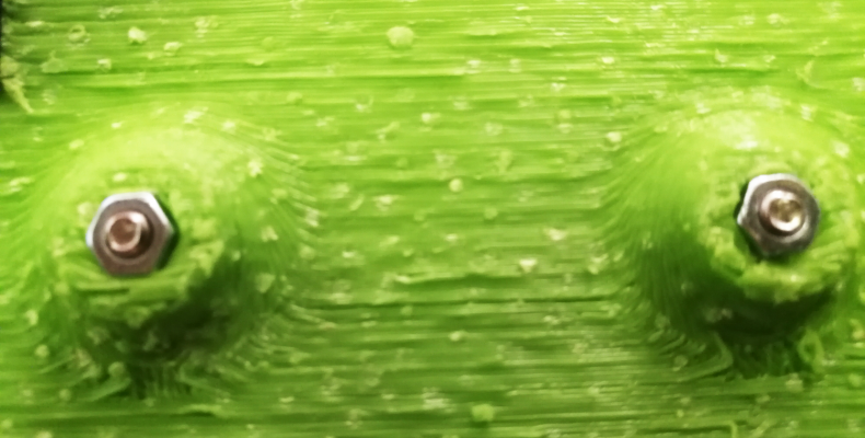
1. Quick & Dirty – insert nuts
If it has to be fast and cheap, I plan an inlay nut into the part.
For this you can plan a slot somewhere in the middle of a hole where you can insert a standard nut.
If you make the slot just a little wider than the minimum width of the nut, you also have an anti-twist protection of the nut and don’t have to look around for a wrench or screwdriver to lock when tightening the screw.
I use this method very often with prototypes and when I realize private projects, because it means a little more effort in CAD, but in the realization and the purchase costs is very favorable.
So that you can model this solution faster, I have attached my help table here:
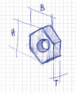
| Size | Addition | Width (B) | Height (H) | Depth (T) | empirical value |
|---|---|---|---|---|---|
| M2 | normal | 4.1mm | 4.65mm | 1.65mm | theoretical |
| M3 | normal | 5.5mm | 6.1mm | 2.3mm | rather tight for FDM, but can be pressed |
| M3 | stop nut | – | – | – | – |
| M4 | normal | 7.0mm | 7.75mm | 3.05mm | theoretical |
| M5 | normal | 8.0mm | 9.05mm | 3.75mm | theoretical |
| M6 | normal | 9.9mm | 11.2mm | 4.85mm | theoretical |
| M6 | stop nut | 9.9mm | 11.2mm | 5.95mm | theoretical |
| M8 | normal | 12.9mm | 14.7mm | 6.35mm | theoretical |
2. professional – ENSAT thread inserts
There are several types of ENSAT thread inserts. I only know two of them.
The first one I know works by using heat (a special tool or soldering iron) to melt the metal insert into plastic.
The second one I use can be screwed into the plastic part using a special tool (if you can afford it) or a normal screw and two lock nuts (as I do at home).
In order for it to work properly, it is necessary to plan the holes in the model according to this table + the rule of thumb at the lowerlimit. Because I use these drillings more often, I have stored these tables in the CAD (Autodesk Inventor) as a table.
Source: http://www.groneman.nl/SiteFiles/Doc/Verbindingstechniek/KerbKonus/Brochure%2030%20-%2030.0714%20Plastics%20and%20Wood.pdf

Once you have screwed the insert into the plastic part, it will be really tight. So you can loosen and tighten the screw 1000 times without any problems.
The disadvantage of this solution is that the inserts are quite expensive. With the Chinese export dealers of my choice, I found so far only those, which one can press with warmth into the component and I personally dont like this method.
Minimum dimensions for screws
And because I’m already throwing tables around here, here’s my auxiliary table with minimum dimensions for screws.
Every now and then you have to save almost every hundredth of a millimeter. Or press a screw into a component, I have this table at hand:
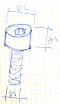
| Screw | D1 | D2 | H1 |
|---|---|---|---|
| M3 | 3.0 | 5.4 | 3.0 |
| M4 | 4.0 | 6.9 | 3.9 |
| M5 | 5.0 | 8.4 | 4.9 |
| M6 | 6.0 | 9.9 | 5.8 |
| M8 | 8.0 | 12.9 | 8.0 |
Better+0.2mm at all masses, because 3D-printed holes are getting smaller!!
 Ben learnt the mechanical craft from scratch in the workshop and then as a technical merchant. He then worked for a few years as a database programmer.
Then he studied mechanical engineering.
And he has completed some CAS trainings in Data Science.
Today he develops special machines for a special machine construction company in Switzerland.
In 2014 he founded the FabLab at Winterthur, Switzerland.
He's main hobbies are his girlfriend, inventing new things, testing new gadgets, the FabLab Winti, 3d-Printing, geocaching, playing floorball, take some photos (www.belichtet.ch) and mountain biking.
Ben learnt the mechanical craft from scratch in the workshop and then as a technical merchant. He then worked for a few years as a database programmer.
Then he studied mechanical engineering.
And he has completed some CAS trainings in Data Science.
Today he develops special machines for a special machine construction company in Switzerland.
In 2014 he founded the FabLab at Winterthur, Switzerland.
He's main hobbies are his girlfriend, inventing new things, testing new gadgets, the FabLab Winti, 3d-Printing, geocaching, playing floorball, take some photos (www.belichtet.ch) and mountain biking.