Mesh Mixer Tutorial
Over Christmas and New Year, one or the other of you will have time to have a look at the 3D printer. That’s why I’ve created a tutorial here that introduces you to Meshmixer and gives you an idea of how powerful Meshmixer really is.
In this tutorial we will make (merge) 2 STL files into one, make a solid (solid part) out of it and then cut away a part of it.
You have to download the program, which is free of charge, and then the STL files, which you need in the tutorial:
Program http://www.meshmixer.com/download.html
STL file of zheng3 http://www.thingiverse.com/thing:354008/#files
Basic navigation in Meshmixer
The operation of Meshmixer is quite simple and with the following commands you will get very far:
Rotate: mouse wheel pressed
Move: Mouse wheel pressed & Shift
Zoom: Rotate mouse wheel & Shift or mouse wheel pressed & CTRL
The Tutorial
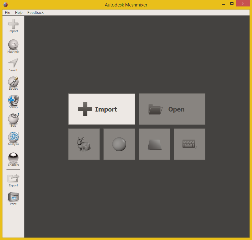
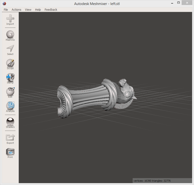
First we click on import and select the left side of the component.
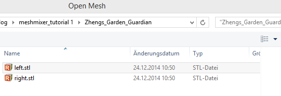
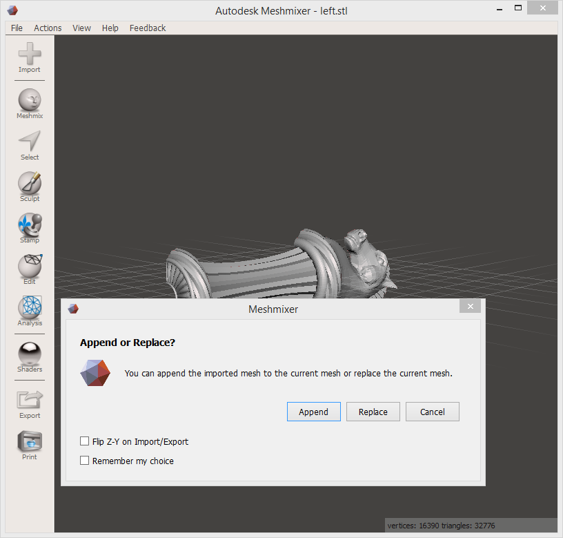
Afterwards we want to add the second page to the project, too, by clicking on the button “Import” again and selecting the right page.
A dialog box appears with the options “Append”, “Replace” and “Cancel”.
At this point we choose “Append”, because we want both parts in the project.
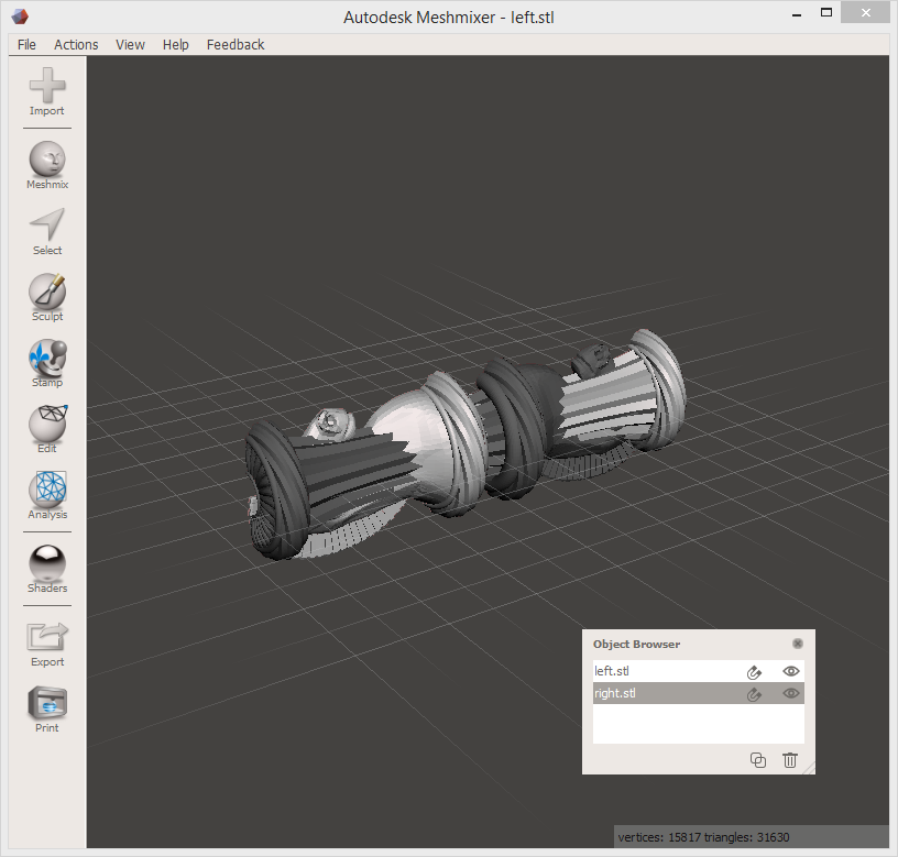
Now both components are in the project. But they are lying useless on top of each other. What is also noticeable now is that somewhere an additional window has opened with the name “Object Browser”. In this window we can select one part at a time. We take nund als rechts, but in the end we don’t play such a role.
Now we go in the right menu bar to the point “Edit”, after that a second one appears right beside the menu with many different points. Now we select the point “Transform” so that we can rotate, move and scale the component.
First we want to rotate the right component by 180° by clicking on the green arc, which is now displayed. If we now pull or push on it, the part will rotate on the green plane. To the right of it the angle is always shown in a small field.
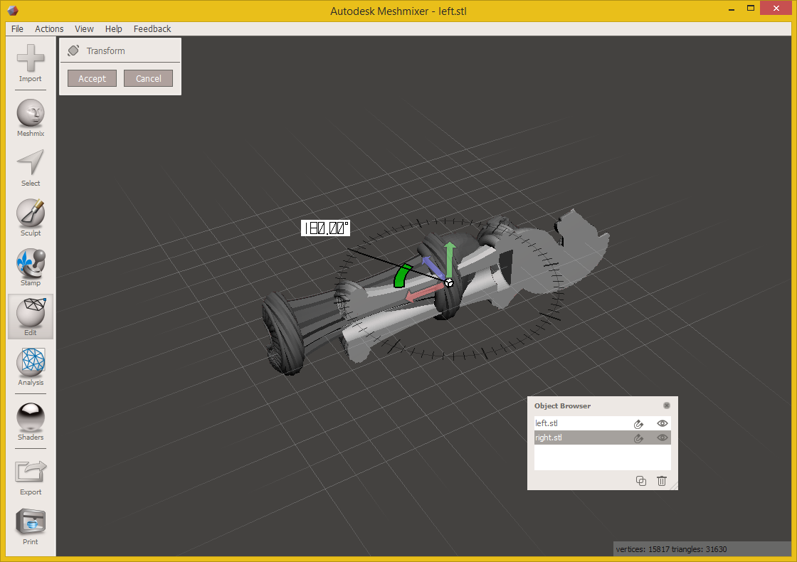
In order to align the component exactly, we now use the mouse to find the divided black circle, which can also be seen in the picture below, and place our mouse on it. After we have turned the part by 180°, we push it with the blue and red arrow on the planes to the right place.
I then checked this optically by looking at it from different angles and in a zoomed state.
What is noticeable now is that the part looks pretty rough, but we’ll change that later.
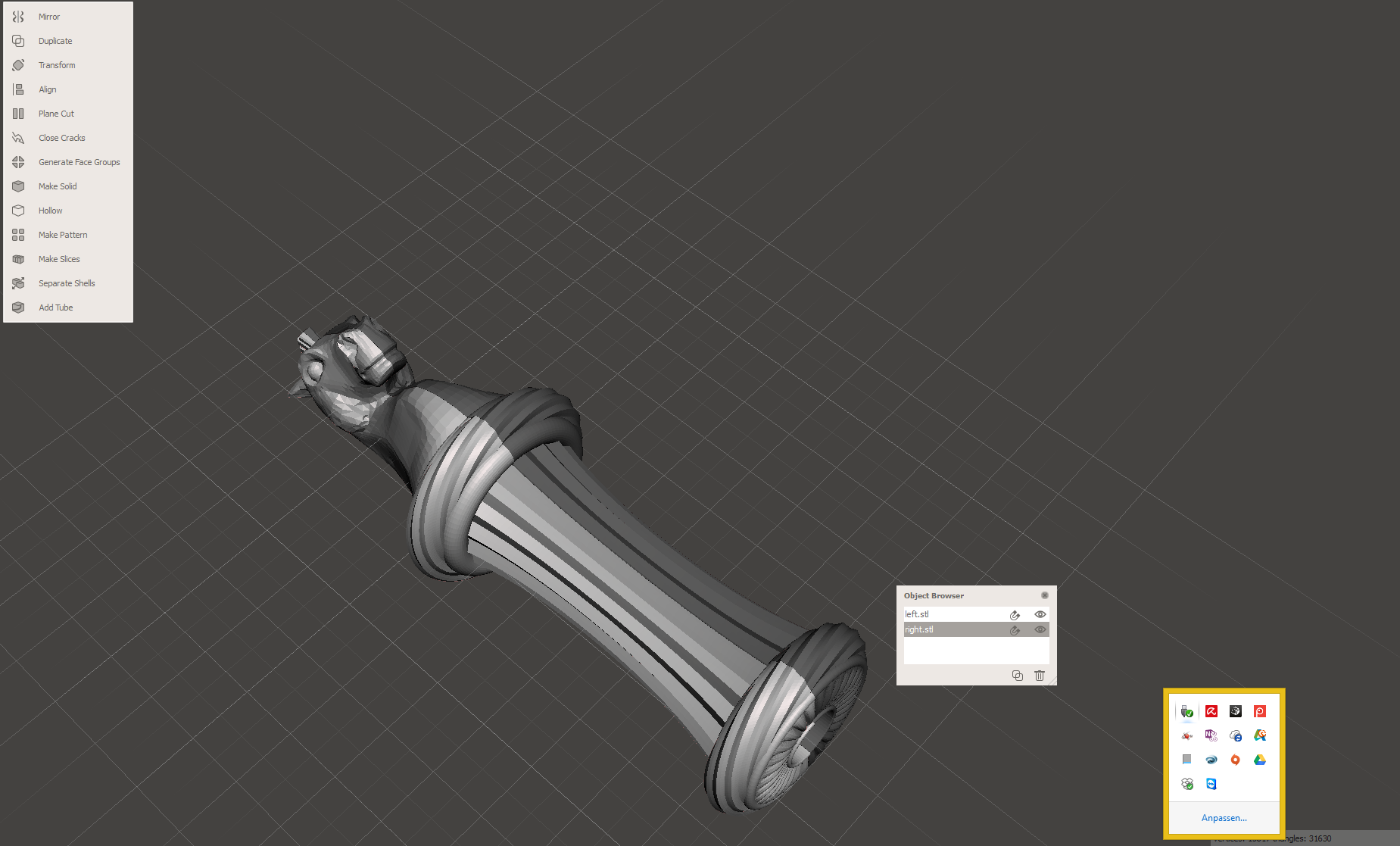
Now we go into the “Object Browser” window and select both components while holding down the CTRL key.
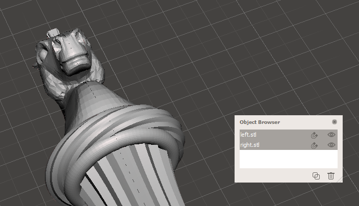
Now we change in the menu “Edit” from “Transform” to “Combine”.

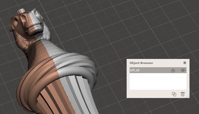
The two parts have now been merged into one, which is now also visible in the “Object Browser”. Now we only have one part left.
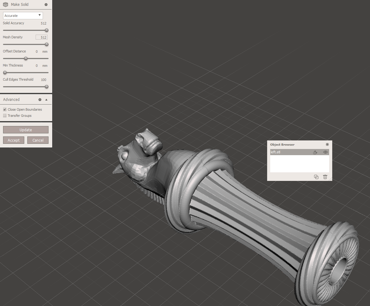
Now we turn the STL file, which is only a shell model, into a solid component and also increase the quality. (This part needs some patience now, because it is quite computation intensive.)

To do this, we select “Make Solid” in the “Edit” menu on the right and play a little with the sliders.
The Update button allows us to view the current settings without having to apply them directly. If we are satisfied, we press the button “Accept”.
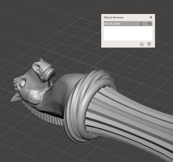
The component now looks a bit nicer again.
At this point, I personally would save the file with CTRL & S, since you certainly don’t want to take the whole calculation process on you, if the program or the PC crashes. So you simply save the Meshmixer project file and no STL file yet.

Now we have two objects in the “Object Browser” again, the STL envelope file and the new solid file. Now we mark the envelope file and click on the trash at the bottom, because we only need the solid model.
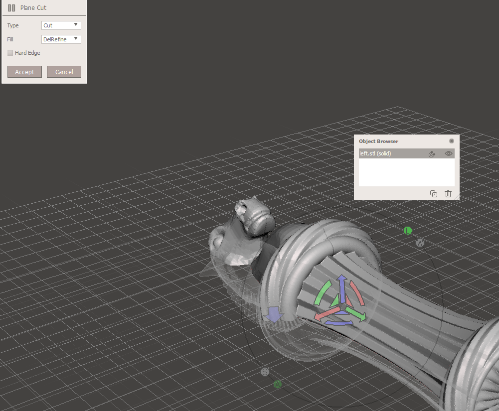
We now want to cut this off at the bottom. To do this, select “Plane Cut” from the “Edit” menu.

Now we have a layer that we can move and where the part is cut. This time we grab the red pitch circle and rotate it. Since we want exactly 90°, we look for the dotted black circle, where our mouse snaps in 5° distances and rotate 90°.
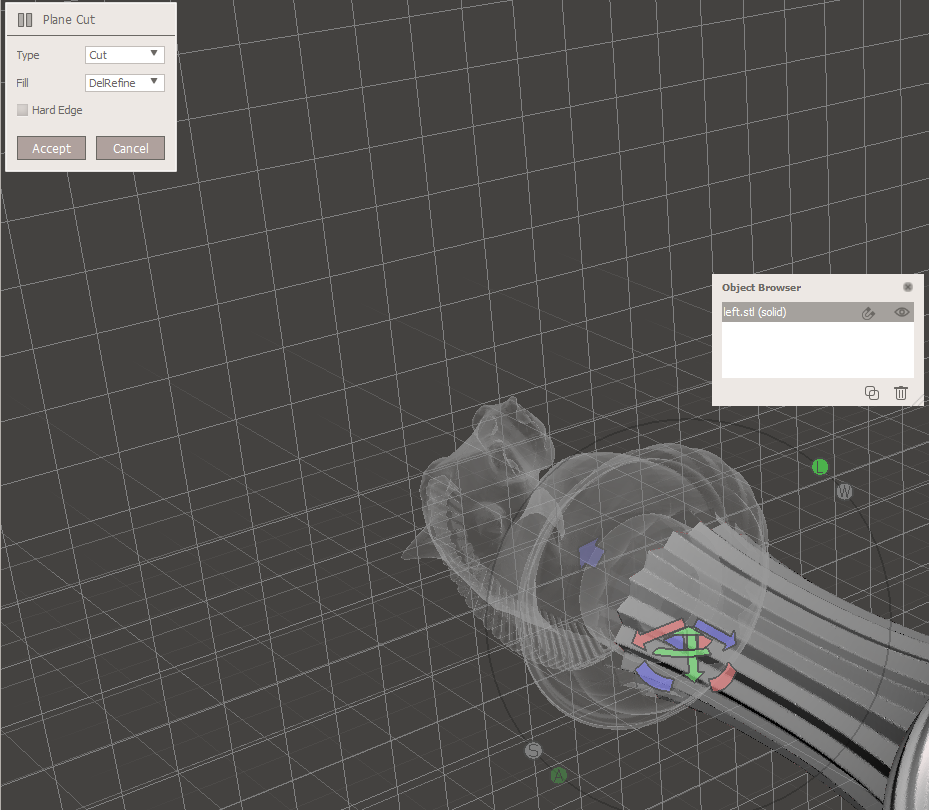
Now we can let go. The change is not yet adopted. But what we see is that the front part that we want to cut away looks fixed and the back part that we want to print is just a transparent net.
This would mean that we would cut away exactly the wrong part. That’s why we rotate the layer again, this time by 180°.
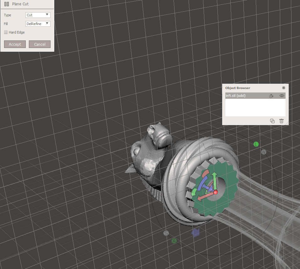
Now the assessment should look something like this. We see that the part we want to print looks solid.
But I want to cut the lower part away from the column. I move the layer over the blue arrow until I am satisfied.
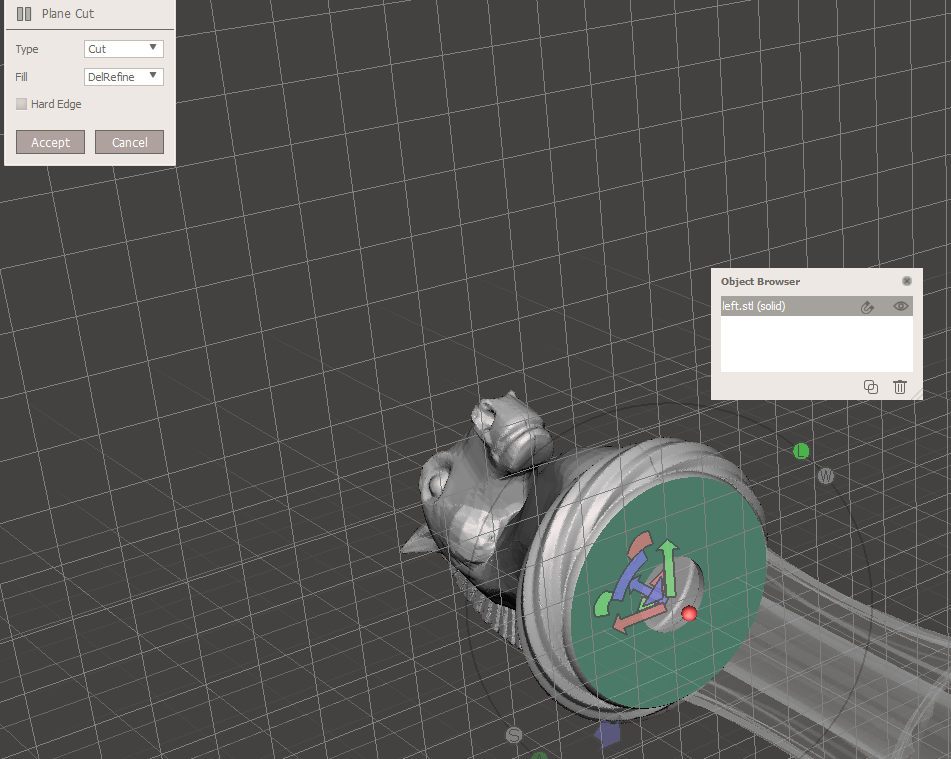
That’s how I want to print it now. That’s why I now execute the cut command by pressing the button “Accept”.

Now we have to export the part as STL so that we can load it into the slicer of your choice and print it afterwards.
This can now be easily done via the menu item “File/Export”.
At the bottom of the dialog we select the STL format and press save.
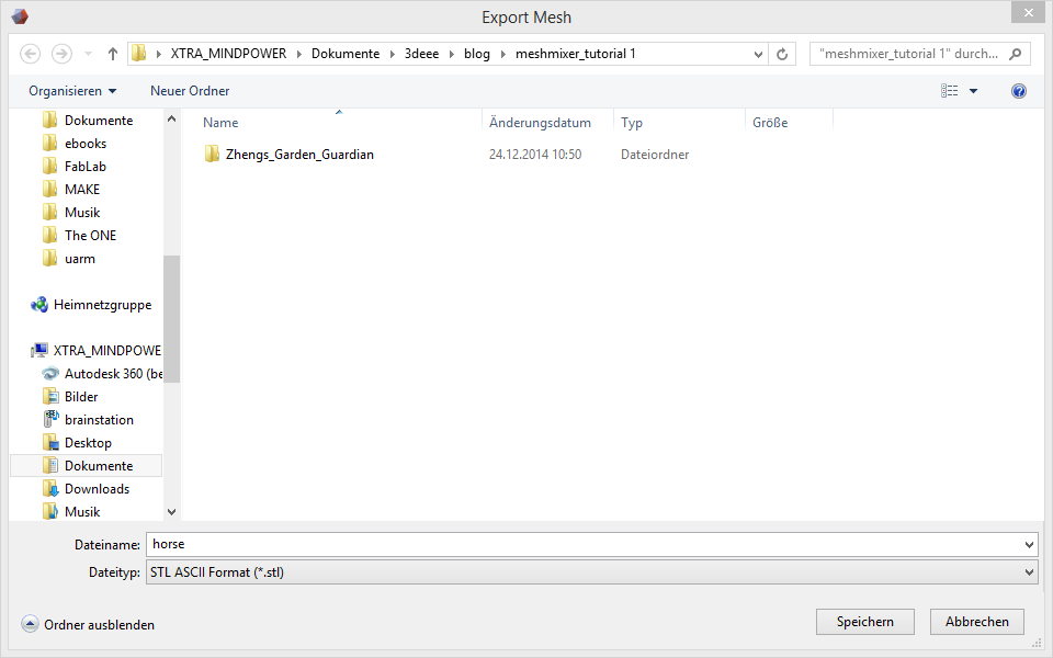
Now you are ready to send the component to the printer.
What I didn’t mention in this tutorial is that I added some support material with Meshmixer, so I can print it really nice. I already wrote a tutorial about this a long time ago, which you can find here: http://www.3deee.ch/?p=525
Have a good time.
Translated with www.DeepL.com/Translator
 Ben learnt the mechanical craft from scratch in the workshop and then as a technical merchant. He then worked for a few years as a database programmer.
Then he studied mechanical engineering.
And he has completed some CAS trainings in Data Science.
Today he develops special machines for a special machine construction company in Switzerland.
In 2014 he founded the FabLab at Winterthur, Switzerland.
He's main hobbies are his girlfriend, inventing new things, testing new gadgets, the FabLab Winti, 3d-Printing, geocaching, playing floorball, take some photos (www.belichtet.ch) and mountain biking.
Ben learnt the mechanical craft from scratch in the workshop and then as a technical merchant. He then worked for a few years as a database programmer.
Then he studied mechanical engineering.
And he has completed some CAS trainings in Data Science.
Today he develops special machines for a special machine construction company in Switzerland.
In 2014 he founded the FabLab at Winterthur, Switzerland.
He's main hobbies are his girlfriend, inventing new things, testing new gadgets, the FabLab Winti, 3d-Printing, geocaching, playing floorball, take some photos (www.belichtet.ch) and mountain biking.