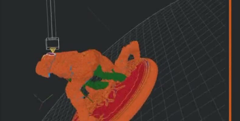
Ever since I started 3D printing about 12 years ago, I have dreamed of printing not just in flat layers, but also non-planar and with a fourth or fifth axis.
Even back then it bothered me that we first have to cut three-dimensional objects into lots of thin horizontal layers, only to put them back together into a three-dimensional object afterwards. That works pretty well, but it also has some drawbacks. In particular the anisotropy, meaning the different strength depending on the direction of the load, and the sometimes very elaborate support structures kept me busy again and again.
With additional axes you could tilt and rotate the print head or the print bed, for example to print overhangs without support, to follow curved surfaces or to build up parts in different directions.
Over the years I read many scientific papers on these topics and at some point even started designing and building my own 5-axis 3D printer.
After I had finished the first three axes, though, it suddenly occurred to me that something rather crucial was still missing.
The slicer!
What good is a printer with five axes if I don’t have any software that calculates the corresponding toolpaths?
Of course I could have finished building the machine anyway and programmed the movements by hand. But I didn’t just want to move a print head around a part. I actually wanted to be able to print arbitrary 3D models with multiple axes.
As far as I knew, there was no freely available software at the time that matched what I had in mind.
So I put the unfinished project on ice and turned to other projects.
A few years later
About three years ago I came across another scientific paper that dealt with slicing in multiple dimensions.
The authors had even written software for it and published it on GitHub.
Of course I had to try it right away!
So I downloaded the source code and tried to install the software. Unfortunately without success. After a few attempts I looked at the GitHub issues and found that I was apparently not the only one who had failed.
A pity, because the method looked really promising.
And so the topic disappeared from my focus for a few more years.
Vibe coding and old ideas
About two to three months ago I started using AI to develop my own software that I had wanted for a long time.
First I set out to program my own replacement for Adobe Lightroom and Photoshop. That was before I discovered the ArtCraft project.
After that I thought about what other software I could use and started developing my own CAD program. Until I came across SolidCraft.
At some point my old 5-axis 3D printer came back to mind.
It would actually be much more interesting to finally develop a slicer that not only supports the usual three axes, but also handles different methods for non-planar and multi-axis 3D printing.
With that I might actually be able to finish the printer project I started so many years ago.
So I started developing my own slicer.
And since I was at it anyway, I didn’t want to build just a small experimental slicer that supports a single method, but a complete slicing application that can hold its own against the established programs.
multiAxisSlicer
Well, here it is: the multiAxisSlicer.
A slicer written in Rust for FDM printers with three to six axes, which, at least in theory so far, works surprisingly convincingly.
The software consists of a normal planar slicing engine, which is meant to roughly reach the functional level of OrcaSlicer, and several additional methods for non-planar and multi-axis printing.
Among other things, the planar slicer supports Arachne walls with variable line widths, classic and tree supports, various infill patterns, multiple build plates and tools for painting on supports and seams. Text embossing and boolean mesh operations are also part of the feature set.
This should make multiAxisSlicer useful for perfectly ordinary 3-axis printers too.
But of course things get interesting with the additional slicing methods.
Non-planar and multi-axis 3D printing
I have currently integrated several methods, some of which are based on scientific work and take different approaches.
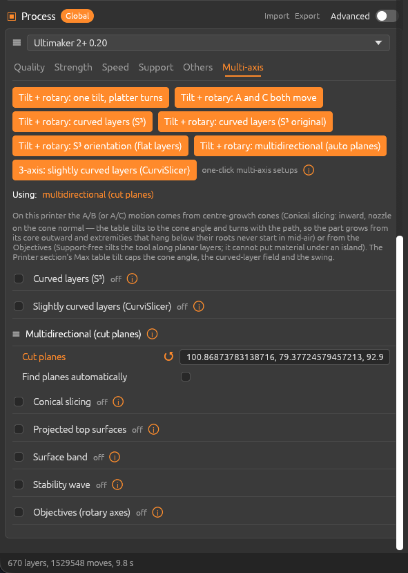
Conical slicing
Conical slicing is based, among other things, on the work on the RotBot at ZHAW.
Instead of cutting an object into horizontal layers, conical layers are generated. For this, the part or the print head has to be able to tilt or rotate accordingly.
There is also a variant in which the cones grow outwards from the centre.
S³ slicer
With the S³ method, curved layers are calculated whose shape follows the geometry of the part.
Overhangs, strength and surface quality, among other things, can be taken into account.
I find this approach particularly interesting because it doesn’t just change the print direction, it also lets you influence the path of the individual extrusion lines.
CurviSlicer
CurviSlicer takes a somewhat different approach and generates slightly curved layers that can also be printed on normal 3-axis printers.
To do this, the geometry is adjusted so that the toolpaths can still be executed with the three linear axes despite the curved layers.
This could be particularly interesting for parts where you want to improve the layer orientation without having to rebuild the whole printer.
Non-planar top surfaces
Another feature is non-planar top surfaces.
Anyone who has ever printed a slightly domed surface on an FDM printer knows the typical stair-stepping caused by the individual layers.
If you print the top layers along the actual surface instead, you could reduce these steps considerably.
For this, the print head has to follow the three-dimensional contour, which among other things requires collision checking.
Multidirectional planar printing
Personally, I find this one of the most exciting methods.
Here a part is divided by several cut planes into multiple regions, each of which can then be printed in a different direction.
Imagine, for example, a figure stretching one arm out to the side.
Normally you would have to build up the arm with support structures, because the layers run horizontally.
With a tilt-rotary table you could rotate the figure after printing the body and then print the arm in a different direction.
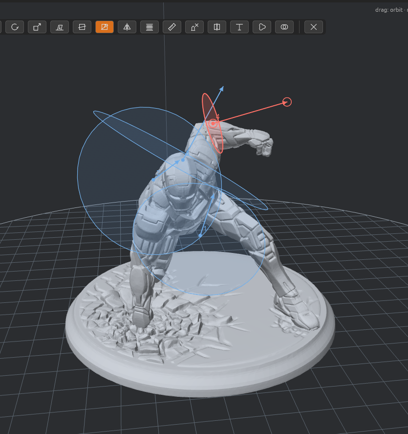
In multiAxisSlicer the cut planes can be placed manually, calculated automatically or limited in size.
The latter is especially handy if, for example, you only want to cut off an arm without the cut plane also running through the rest of the body.
Of course, the whole thing is a bit more complicated than it sounds here, because the individual regions have to be printed in the right order and the machine must not collide with the part that has already been printed.
Collision checking and simulation
On a normal 3D printer, the possible movements of the print head are relatively easy to calculate. On a machine with four, five or six axes, things get considerably more complicated.
Especially on printers with tilt-rotary tables, you have to take into account that not only the print head but also the already printed part moves through space.
That’s why I have integrated several checks.
Before the G-code is exported, the software checks whether the tool and machine could collide with the part, whether material would be extruded into thin air without sufficient support, and whether the required movements stay within the mechanical axis limits.
There is also a machine view in which you can simulate the entire print, including the movements of the print head and the tilt-rotary table.
This is particularly helpful for the multidirectional methods, to see whether the calculated toolpaths can actually be executed sensibly at all.
The G-code can be output in various dialects, including variants with indexed rotary axes, such as those used by the Fractal 5 Pro.
Desktop app, browser and command line
multiAxisSlicer is built so that the actual slicing engine can be used independently of the user interface.
There is a desktop app with a 3D view in which models and cut planes can be moved and rotated with gizmos. A command line and a browser console are also available.
Prepared build plates, including their settings, can be saved as a .masetup file and opened again later.
The source code is licensed under AGPL-3.0. The algorithms used and adapted are documented with their sources in NOTICE.md.
I haven’t published the project yet, though, because I first need to remove or replace some test models in the repository that I’m not allowed to simply pass on.
Does it actually work?
Well, that’s a good question. 😉
So far I have mainly tested the various methods in the software. The generated toolpaths look good in the simulation, the machine movements are calculated and the corresponding G-code can be generated.
But that doesn’t mean by a long shot that you can actually print usable parts with it.
Especially with the non-planar methods, there are many things that will only show up in practice. For example, whether the calculated distances to the surface are right, how the molten filament behaves in different print directions, or whether the machine can really execute all the movements cleanly.
So I expect to run into one problem or another during the first test prints.
But at least I finally have software that lets me run such experiments in the first place.
Now all that’s missing is the printer
Which brings me back to my original project.
I currently have two options.
Either I convert an old Ultimaker 2 Extended+ that I still have here, or I get down to finishing my old self-built machine.
For the electronics I already have a BIGTREETECH Octopus Pro, on which I could run Marlin. Although I still need to check how well the additional axes and their movements can actually be implemented with it.
The module for the fourth and fifth axis, a tilt-rotary table, is also ready and waiting.
So really, not that much is missing anymore.
Then again, I probably thought the same thing twelve years ago. 😉
I’ll probably have to decide first which machine I want to convert, and then start the first practical experiments with the different slicing methods.
I’m especially curious about conical slicing and multidirectional printing, as these should finally let me try out some of my original ideas.
Maybe I’ll actually manage to finish the 5-axis printer I started about twelve years ago.
And if the whole thing doesn’t work, at least I’ll once again have learned quite a lot about 3D printing, geometry and software development.
I’ll keep you posted. 😉
 Ben learnt the mechanical craft from scratch in the workshop and then as a technical merchant. He then worked for a few years as a database programmer.
Then he studied mechanical engineering.
And he has completed some CAS trainings in Data Science.
Today he develops special machines for a special machine construction company in Switzerland.
In 2014 he founded the FabLab at Winterthur, Switzerland.
He's main hobbies are his girlfriend, inventing new things, testing new gadgets, the FabLab Winti, 3d-Printing, geocaching, playing floorball, take some photos (www.belichtet.ch) and mountain biking.